|
|
|
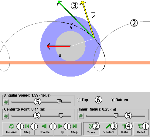
Click on a number to view the explanation of the corresponding item.
There are six basic control buttons. They are, from left to right:
 Rewind. Resets the simulation to the initial
position with the previously chosen initial values. If
the path is displayed, Rewind will allow you to compare
paths traversed under different conditions, e.g.,
different initial velocities.
Rewind. Resets the simulation to the initial
position with the previously chosen initial values. If
the path is displayed, Rewind will allow you to compare
paths traversed under different conditions, e.g.,
different initial velocities.
After clicking Rewind, click Play to restart the motion.
 Step. Lets you step through the motion in equal
time steps going from right to left.
Step. Lets you step through the motion in equal
time steps going from right to left.
 Reverse/Pause. Starts the motion in reverse
direction, i.e., from right to left.
Reverse/Pause. Starts the motion in reverse
direction, i.e., from right to left.
After REVERSE has been clicked, the button will
change into the PAUSE button  .
.
Clicking PAUSE will freeze the motion. To resume the reverse motion, click REVERSE once more.
 Play/Pause. Starts the motion in forward
direction, i.e., from left to right.
Play/Pause. Starts the motion in forward
direction, i.e., from left to right.
After Play has been clicked, the button will change
into the Pause button .
Clicking Pause will freeze the motion. To resume the motion, click Play once more.
 Step. Lets you step through the motion in equal
time steps in the forward direction, i.e., from left
to right.
Step. Lets you step through the motion in equal
time steps in the forward direction, i.e., from left
to right.
 Reset. Resets the applet to its default
setting.
Reset. Resets the applet to its default
setting.
Adjustments in the initial conditions can only be made after first clicking REWIND or RESET.


This toggle button displays/hides the path of the moving point.

The Vectors toggle button displays/hides the vector panel shown below.

Check the checkbox for a vector to display that vector. Three velocity vectors can be displayed:
 of the point on the spool relative to the lab
frame,
' of the point on the spool relative to the
frame translating with the spool,
of the point on the spool relative to the lab
frame,
' of the point on the spool relative to the
frame translating with the spool,
 of the frame translating with the
spool relative to the Lab frame.
of the frame translating with the
spool relative to the Lab frame.
When the motion is paused, the velocity vector
can be
dragged. By placing it so that its tail end is at
the tip of the velocity ', you can demonstrate that the
three velocities satisfy the Galilean velocity
addition theorem: = ' + .
 .
.
The Data toggle button displays/hides the two data boxes illustrated below. The two boxes can be dragged separately. The box on the left displays quantities that are constant during the motion and the elapsed time. The box on the right displays the coordinates of the revolving point in two frames of reference and the coordinates of the center of the spool.

The x and x' axes point to the right and the y and y' axes upward.

There are three sliders in all. They are described below, in the order from top left to bottom right.
You can adjust a slider setting either by dragging the slider tab or by entering an exact value in the slider input dialog.
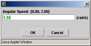
To enter an exact value, click on the Input Dialog button
 of the slider to open the dialog. The dialog
for the Angular Speed slider is illustrated below. The
range in which values can be entered, from 0 to
2.00 rad/s in this case, is indicated above the data
entry field.
of the slider to open the dialog. The dialog
for the Angular Speed slider is illustrated below. The
range in which values can be entered, from 0 to
2.00 rad/s in this case, is indicated above the data
entry field.
Clicking on a slider to the left or right of the slider tab allows fine adjustment of the slider setting.

Top: select this radio button to have the spool's inner cylinder supported from above, as in the following snapshot.

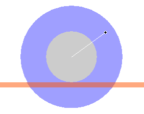
Bottom: select this radio button to have the spool's inner cylinder supported from below, as in the following snapshot. This is the default setting.